Couriers
| Couriers provide two dimensional motion for products, both for gross movement from point to point in the factory and for fine positioning when coordinating with other agents, such as manipulators. Thus couriers replace both conveyor belts and (in conjunction with 2-DOF manipulators) the need for 4-DOF assembly robots. Couriers can move up to about 1.5 m/s along an arbitrary path over several meters and position themselves with a resolution of about 200 nm using integral sensing and closed-loop control. They can also precisely rotate up to about ±2°. | 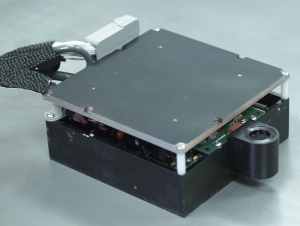 |
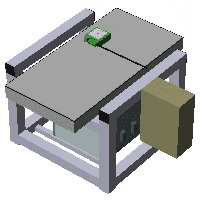
Move your mouse over the rendering above (click on the image if your browser does not support rollovers) to see descriptions of a courier (items in blue). Some details are shown in the smaller black lettering. The product sub-assembly is shown in orange, and parts are shown in red.
A courier is an "agent," i.e., it has its own computing resource and executes its own program rather than being controlled by a central system. Couriers must coordinate with the other agents in the minifactory to successfully carry out their operations.
 |
 |
|
|
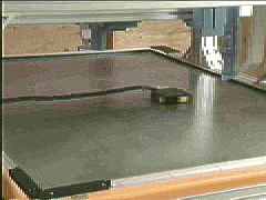
View a real courier doing a figure-8.
|
A "courier" consists primarily of a brain box (tan color in the figure above) and a closed-loop planar motor (in solid green in the figure). The brain box contains all of the computing and other electronics for the courier agent, and is connected via a tether (black line) to the planar motor. The tether carries power, air, and all control signals between the brain box and the motor. The brain box is clamped to a base unit, and connected to the service infrastructure (power, air, vacuum, and network) of the minifactory. Couriers also have a precision optical coordination sensor and a modular vise for holding the product.

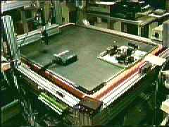 |
View a courier doing fast moves.
|
Actuation
The courier planar motors consist of a moving forcer that can translate in two directions in an open-loop mode along a passive steel platen stator surface with a waffle-iron type pattern, originally developed by Bruce Sawyer in the late 1960s. The forcers fly on a 12-15 micron thick air bearing preloaded with permanent magnets. A tether from the brain box provides the air supply and power. These forcers and platens are available commercially both as separate components and integrated into assembly workcells. The particular prototype forcer we show here is the Normag 4XY1302-2 planar motor, with 1.016 mm tooth pitch, 26 N nominal static force, 0.7 Kg mass, and 2 A operating current. Two motors in each direction generate balanced forces about the center of mass. (Here, motor refers to one of the four actuators on the forcer, and planar motor refers to the entire device, or forcer.)
We have designed our own courier forcers for minifactory from the ground up, including finite element magnetic analysis, design of laminations, fabrication and stacking of laminations, CNC coil winding, machining, and final assembly. Because we have developed an entire manufacturing process for both couriers and platens, we can control their characteristics and optimize the design for high-performance closed-loop operation. Currently, our couriers are U.S. patent pending.
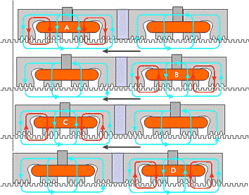 Each of the four motors contained in a forcer consists of a stack of laminations and two coils, shown here schematically . The motors operate on a flux-steering principle, with the coil currents acting to switch the magnetic flux from one set of poles to the other. The poles with the most flux tend to align themselves with the platen teeth, so that by activating the poles in the proper order, a stepping motion is achieved. The coil currents can also be microstepped by applying a sine wave to one coil and a cosine wave to the other.
Sensing
Although these motors have found some success in industry, their normal open-loop operation does not give the robustness, performance, and versatility needed for use in a minifactory. For example, as commanded speeds are increased, the motor will begin to lose synchrony and stall in an unpredictable way. In addition, open-loop operation can not provide sufficient rejection of disturbance torques during assembly operations. Closed-loop control can solve these problems, eliminating stalling and permitting programable compliance and force control. Robust closed-loop control of planar motors has not previously been successful because of the lack of a suitable position sensor.
 |
 |
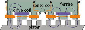
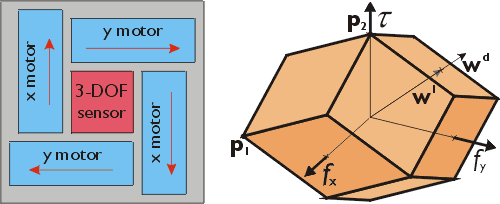
Our group has developed an ac magnetic sensor that is incorporated into the forcer for sensing platen teeth to a resolution of 200 nm (1 sigma). This sensor provides high precision positioning capability over the entire forcer workspace. We have explored both optical ![]() and magnetic sensing schemes, and have fabricated a compact 3-DOF magnetic sensor.
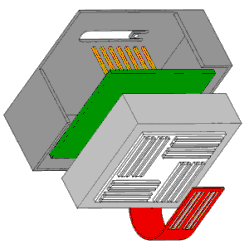
and magnetic sensing schemes, and have fabricated a compact 3-DOF magnetic sensor. ![]() In the figure on the left, above, a section of the sensor is shown schematically depicting how ac magnetic flux couples into the platen surface. As the courier containing the sensor moves along the platen, variable amounts of this flux are picked up by sense coils, permitting reliable measurement of position to about one part in 5000 of the platen tooth pitch. In the figure on the right, above, four such elements are shown integrated into a single monolithic substrate, allowing precise measurement in three degrees of freedom. The sensor is housed in the (otherwise unused) center portion of the forcer as shown below.
In the figure on the left, above, a section of the sensor is shown schematically depicting how ac magnetic flux couples into the platen surface. As the courier containing the sensor moves along the platen, variable amounts of this flux are picked up by sense coils, permitting reliable measurement of position to about one part in 5000 of the platen tooth pitch. In the figure on the right, above, four such elements are shown integrated into a single monolithic substrate, allowing precise measurement in three degrees of freedom. The sensor is housed in the (otherwise unused) center portion of the forcer as shown below.
| Shown here is the resolution performance of one of our prototype 3-DOF ac magnetic position sensors. The upper plot is the output from a single sensor pair vs. sample number with the courier stationary as measured by laser interferometry. These data are plotted in histogram form on the bottom plot, indicating a 200 nm (1 sigma) resolution at a bandwidth of more than 10 kHz. | 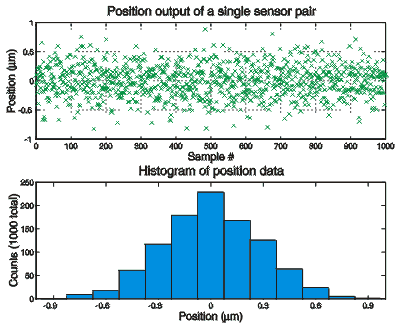 |
Control
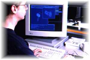
Although our high precision sensor enables closed-loop control, complications remain. Models for the actuators are required to cancel non-linear effects such as magnetic saturation, eddy-current damping, and rotational dependencies. We have used interferometer and load-cell test systems to study these effects and develop appropriate models. ![]()
![[Picture]](images/arthur2.png)
 These models have been incorporated in a software commutator shown above in the block diagram, that does its best to make the four stepper motors act like linear servo motors. We have also demonstrated self-calibration of these models by exploiting the redundancy of the actuators and sensors. The force resolution block handles the actuator redundancy by appropriately mapping the controller's output wrench (a vector consisting of an x force, a y force, and a torque) to force commands for each of the four linear motors. In cases where the controller wrench is larger than can be generated by the actuators, the force resolution block also maps it back on to the envelope of achievable wrenches. For example, the desired wrench wd shown lies outside the envelope of achievable wrenches (which is a rhombic dodecahedron for our actuator configuration, see diagram above), and is linearly scaled to wrench wl before being converted into forces for the individual actuators.
To see the advantages of closed-loop control, we used a U.S. cent affixed to the courier as a reference feature for viewing by a video microscope. For 70 micron motions, the closed-loop controller appears dramatically crisper than the open-loop controller. To see this interesting result, check out Arthur's Famous Penny Demo.
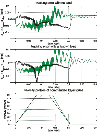
The plots above show tracking errors for a larger move for cases where the mass is known (top plot) and unknown (middle plot). In both cases, the open-loop controller errors (shown in green) have oscillations both during and after the move, even when we carefully shape the velocity profile (shown in the bottom plot) in an attempt to avoid exciting motor dynamics. If these oscillations grow to a large fraction of a tooth pitch, the open-loop controller will begin to lose steps. The closed-loop controller (shown in black) eliminates this oscillation, even with an unknown load. In addition, it does not require any special velocity profile and can have arbitrarily large tracking errors without missing steps. ![]()
Optical coordination sensor
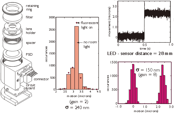
 Couriers are equipped with a high-resolution optical coordination sensor which can detect and localize LED beacons in the 3D minifactory workspace. An important use of this capability is factory calibration, which automatically generates a virtual factory model in precise registration with the as-built factory. In the figure above left, there is an exploded view of our optical coordination sensor which is based on a duo-lateral type lateral effect photodiode (position sensing photodiode or PSD), optical, and electronic filtering. As shown in the plot in the middle of the figure, the resolution (verified by laser interferometry) is 240 nm (1 sigma) even in the presence of strong 120 Hz fluorescent light illumination. The upper right plot shows the sensor output for a courier move of 2.5 micrometers, plotted in histogram form on the lower right, showing a motion resolution of 150 nm (1 sigma).
Modular vise or fixture
Products ride on the backs of couriers in modular vises. The vises are actuated and have arrays of holes in which pegs can be placed to hold the product in place during assembly, while allowing the product to be transferred between couriers when required. For a given product shape, the optimum peg arrangement can be found by application of the Brost-Goldberg algorithm.