AAA Life Cycle
We present here the step-by-step scenario for developing an automated assembly system (factory) within the AAA framework. The scenario is general, but illustrated with a particular instantiation of AAA, namely minifactory.
1. Factory Design
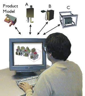
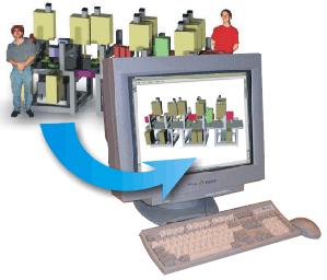
First, a manufacturing engineer (or factory designer) interacts with a comprehensive modeling and simulation environment, the AAA interface tool. Functional models of the factory components are distributed; they reside within each factory module at the geographic location of the module vendor company. When a factory model is generated in, e.g., Pittsburgh, the various robotic modules (agents A, B, and C) which make up the model might by physically located in Akron, or Detroit, etc. Thus the modeler/simulator in Pittsburgh needs no prior knowledge of the components. Further, by accessing and incorporating data from each on-line module remotely (via the Internet), the modeler/simulator has only up to date and reliable information - instead of catalog or faxed data sheet information which might not reflect the currently available module product.
2. Factory Programming and Simulation
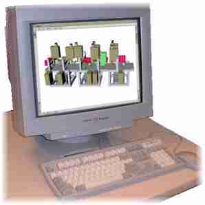
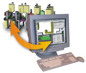
During the creation of the factory design (model), the factory designer is free to select and try out in simulation a wide variety of configurations using modules from many different sources to arrive at a final design (virtual factory). The designer may also make use of various tools such as automated assembly sequence planners, schedulers, layout tools, etc., but that is outside the scope of our current work. The programmer writes programs for each agent, allowing the virtual factory to assemble the virtual product.
3. Module Procurement
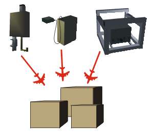
From the perspective of the factory module supplier or vendor, manufacturing modules complying with the AAA paradigm are designed, built, and programmed by traditional means. Modules offered for use are placed "on the shelf" and plugged into the Internet, thereby becoming available to any factory designer. Synchronizing and lockout means are provided to mediate simultaneous engagement by multiple designers. Examples of modules for precision assembly include robotic manipulator/feeders, couriers for transporting subassemblies, glue dispensing equipment, laser processing equipment, metal forming (e.g., swaging, spinforming) equipment, etc. Modules selected by (geographically distant) designers for use in real factories are leased according to usage schedules or other criteria and air-shipped to their destinations ready for set up and work within hours of their arrival.
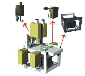
4. Factory setup
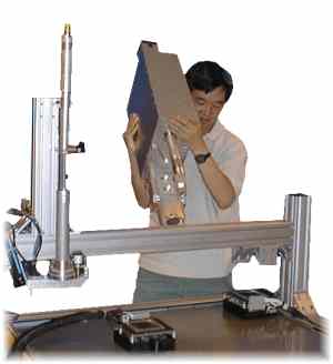
From the perspective of the builder of an AAA factory, who may be geographically separated from both the designer and module vendors, the factory is rapidly set up manually by "snapping together" modules and hooking them up to bused services . This is done by following a plan generated by the interface tool as a by-product of the factory design process. It is neither necessary to configure the factory exactly according to the model, nor to precisely place each of the modular robotic elements. One or more high-performance general-purpose workstations are connected for modeling, simulation, programming, debugging, and operation monitoring.
5. Automatic Calibration
Once the real factory is physically configured and set up, AAA specifies an automated process to begin whereby the factory is automatically calibrated to determine the precise locations and identities of all modular elements as well as the topology and boundaries of the available workspace. This information is broadcast by each robotic agent (module) and collected by the workstation modeler (interface tool). Combined with geometric and functional information from each of the other modules, a complete factory model is automatically generated by the factory itself. This model resembles the original design model, except the new model accurately reflects the "as built" factory.
6. Final programming and debugging
From the perspective of the factory programmer, the factory is programmed manually from an attached workstation using mostly graphical methods. Each active factory module embodies an agent representing it which presents multiple views to the programming environment. For example, the functional controls of a module are accessed and manipulated through its dashboard view. A module's public input and output ports are available through its interface view, etc. The factory is programmed by connecting outputs to inputs and specifying actions to be performed from internal repertoires. For example, a part handled by a manipulator/feeder module can be aligned with and placed on a subassembly carried by a courier module by specifiying a set of coordinating actions which must occur between modules to carry out this task.
7. Distributed execution
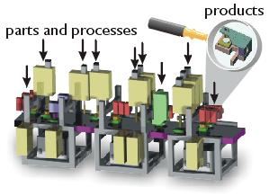
From the perspective of the factory operator, once the factory is programmed, execution takes place in an event-driven, asynchronous manner, without supervisory control at any level. Attached workstations perform monitoring and debugging functions (in event of non-recoverable failures). Supplying the factory with parts on demand is done manually, and removal of finished products is done by other automated or semi-automated means, which are currently outside the scope of AAA.
8. Rapid changeover
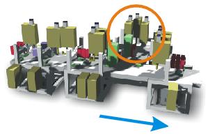
At any later time, the factory can be rapidly reconfigured to respond to changing market requirements. Modules can be added or removed, and new factory models can be automatically regenerated. As shown on the right, a section of the factory has been moved (blue arrow) and a branch has been added (orange circle).
9. Reusability of modules
At any time, modules no longer needed can be returned to the on-line pool for use by other manufacturers. AAA promotes a higher degree of module re-usability than conventional approaches.