An AAA/Minifactory Example
The product
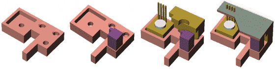
| Shown at right and below is a simple made-up example of a tiny mechatronic sub-assembly which could be part of a larger product. Assembly begins with the pink base part. Next, the purple opto_module must be added using adhesive and vision alignment with one of the holes in the base part. Next, the tan square circuit module must be glued into position and fastened with the circullar silver pin using a compliant assembly strategy. The irregular-shaped brown plug must also be inserted using compliant motion facilitated by the chamfers on the pair of holes in the base part. Finally, the gray top_board must be added and the connections must be welded. | 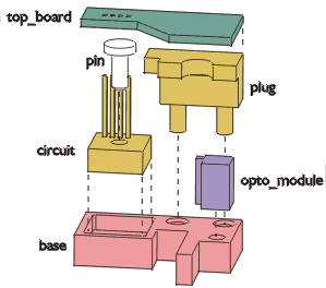 |
The work flow graph
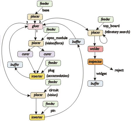
Abstractly, the various actions necessary to turn the collection of parts into a functioning product can be represented by a work flow graph, shown below. Here, the boxes are nodes that the parts and sub-assembly must visit, and the arcs denote physical motion which must occur between the nodes. Nodes such as feeder, gluer, placer, etc. are abstract operations which must be performed. In AAA/minifactory, these operations must be mapped into available agents in order to instantiate the assembly system.
The factory
How would a suitable minifactory for assembling such a product be built? We have a tour of a virtual minifactory, corresponding to what a real minifactory would look like. You will see nine successive steps of building the virtual minifactory, each with an explanation which refers to the corresponding step in a real minifactory. You will start at 12:00. Note the elapsed time on the wall clocks in each step.
If you have Cortona VRML plugin installed, you can see a 3D representation of the (simplified) completed minifactory (163K download). Use the mouse or arrow keys to navigate the scene. Explore the inside of the factory. Don't worry, you can't collide with things.
If you prefer, we also have a video of the above factory in motion. ![]()
What the factory is doing
In the left part of the factory, a precision parts feeder provides base parts to two couriers with the aid of a manipulator. A precision parts feeder provides opto_module parts. A glue dispenser dispenses glue for the opto_module. A manipulator places opto_module parts using vision and force guidance. Ultraviolet light curing stations serve to cure the glue. A manipulator takes plug parts from a bulk feeder and inserts them.
In the center part of the factory, two couriers serve in parallel to move sub-assemblies through this part of the factory. A manipulator takes pin parts from a bulk feeder and inserts them. Another manipulator places circuit parts fed by another precision parts feeder .
In the right part of the factory, the two couriers continue to transport sub-assemblies. A manipulator places top_board parts fed by a precision parts feeder . A laser welder joins the pins of circuit to top_board. A vision inspection station and its associated final product buffer serve to classify and store the finished product.
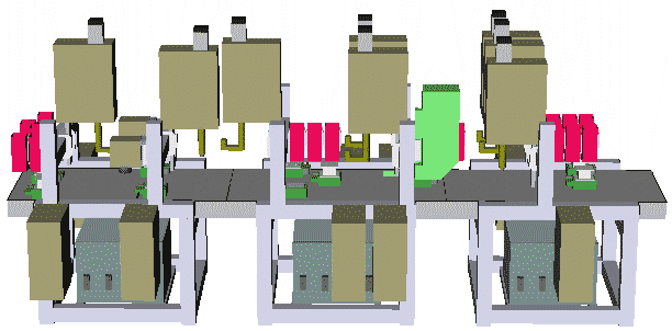
Each of the manufacturing agents in this example is an independent entity, perhaps supplied by different vendors, operating in conjunction with its peers to produce a product. Each agent executes its own program on its own computing resource (brown rectangular boxes).
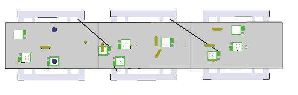
Above is a top view of the factory, with static structures removed by the interface tool to make the moving components visible. (Note that couriers shown without tethers are actually part of the precision parts feeders; their tethers go upward to avoid collisions with the product couriers.). We have a short movie showing a plan view of the factory in motion. ![]()
It is interesting to get a glimpse of the "product's-eye view" by zooming through the factory as the product is being assembled. Highly recommended! ![]()
Once a programmed virtual minifactory is obtained, a corresponding real minifactory can be rapidly deployed. In this case, the minifactory would occupy a floor space of about 1.5 meters by 3.6 meters. We have developed automatic mechanisms within AAA for precisely registering and synchronizing the real and virtual counterparts.
Just for fun: how the factory would look if it were assembled in our lab
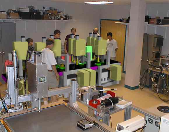
Above, members of the lab admire the (virtual) minifactory. Prototype hardware (real) is in the foreground.
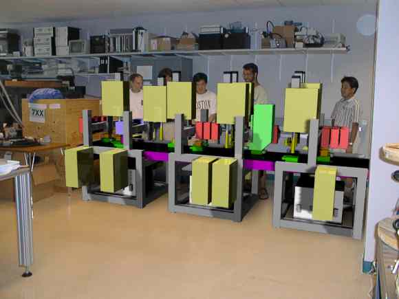
Ben, Jay, Mike, Rich and Shinji discuss several features of this particular factory layout.
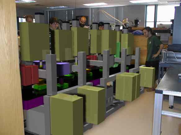
Above, view from the the hallway. Al, Arthur, and Zack join in the discussion.